 English
 Chinese
 Dongguan Hallsen Technology Co., Ltd
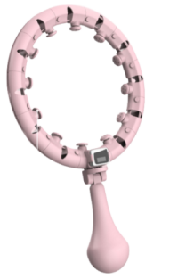
The application principle of the Hall switch in the smart hula hoop: The design goal of the smart hula hoop is to realize the intelligence of motion monitoring and data recording. The Hall switch is used to detect and record the motion state and number of rotations of the hula hoop. In the smart hula hoop, the Hall switch is usually installed in the hoop to monitor the rotation of the hoop by sensing the change of the magnetic field. When the hula hoop rotates, the change of the magnetic field will be sensed by the Hall switch and converted into a corresponding electrical signal, thereby realizing the accurate monitoring and recording of the hula hoop movement. The Hall switch in the smart hula hoop is usually closely integrated with the sensor and the processing unit to form an intelligent motion monitoring system. When the hula hoop rotates, the Hall switch will output the corresponding electrical signal, and the sensor will convert these signals into motion data and send them to the processing unit for processing and analysis. By analyzing the processed data, the smart hula hoop can display the number of rotations, exercise duration, calories consumed and other information in real time, providing users with comprehensive exercise records and guidance.
Recommended model: HS4913 non-polarity low-power Hall chip
HS4913 is a non-polarity Hall switch based on mixed-signal CMOS technology. This IC uses advanced chopper stabilization technology to provide accurate and stable magnetic switch points. In terms of circuit design, HS4913 provides an embedded controlled clock mechanism to provide a clock source for the Hall device and analog signal processing circuit. At the same time, this controlled clock mechanism can send a control signal to make the circuit with large current consumption periodically enter the "sleep" mode; through this mechanism, the chip is periodically "woken up" and detects the magnitude of the magnetic field strength passing through the Hall device according to the predetermined magnetic field strength threshold. If the magnetic flux density is higher than the "operating point" threshold or lower than the "release point" threshold, the open-drain output transistor is driven and latched into the corresponding state. During the "sleep" cycle, the output transistor is locked in its previous state. In battery-powered applications, this design provides the best support for extending the working life.
The output transistor of HS4913 is locked in the on state when there is a certain strong south or north magnetic field facing the package marking side, and is locked in the off state when there is no magnetic field.
